If I’ve got it right, Rutland is going to do some minimal work on the second hand engine before replacing his existing low oil pressure engine in order to rebuild the existing low oil pressure engine and then, for a second time, swapping that back in. Why? If a complete engine rebuild is on the cards why not just rebuild the second hand engine and do the swap once? If the existing engine is that low on oil pressure that a complete failure is imminent then I think a rebuild of it might be a tad risky!
Compression testing is simple on an engine stand - just fit a starter motor and spin it over. If the compression is OK across all cylinders I would leave the top end alone.
Oil pressure will not be such a concern if your newer oil pump is to be fitted. Indeed, once the sump is off (and assuming it’s not full of sludge) I would remove the main and big end bearing caps to check the crankshaft and if OK re-shell the lot. Whilst there do not forget to replace the cruciform seals on the rear main bearing cap. I’d also replace the front crankshaft oil seal as well as the rear. These are all relatively inexpensive items as insurance for the future.
Harv wrote:
I don’t think you should use 100% concentrate. If you’ve flushed the system with water, you could then add the 100% coolant to the pure water left in the system. Then you’ll end up somewhere in the 50% range.
No need for guesswork. After flushing the system through with normal tap water disconnect the top hose and, using Mk1 lung power just blow the remnants of flushed water out of the system. Then disconnect one of the heater hoses and do the same. System will be pretty much completely empty. Reconnect all hoses and refill with 50/50 coolant/deionised water mix. Job jobbed.
You can replace Mk1 lung power (if you don’t have much puff or are too short to get at the heater hoses) with compressed air if you like via a compressor (if you have one) or a foot pump if you don’t (or even a bicycle pump).
Viro-Sol will not harm the tarmac. Any oil/grease coming off the engine/gearbox/axle will be mixed with the degreaser of choice and as long as the tarmac is washed down afterwards will not do any harm.
It won’t work, it’ll just dilute the product to uselessness (is that a word?) for tough stuff!
Save the spray bottles that your household cleaners come in, clean them thoroughly and use them. I have lots with various lotions and potions in them including my favourite degreaser/cleaner in various states of dilution from 10% to neat. I use Viro-Sol - it’s a citrus cleaner that is water soluble and doesn’t harm rubber or paintwork. It also smells lovely.
For the tough stuff (like engines, gearboxes and axles) I use it neat. Spray it on, leave it a few minutes, agitate with a brush and then blast the crud away with the power washer. It’s also brilliant for removing brake dust and grime from wheels - I use it diluted 50/50 with water for this.
Water is the better coolant and 50/50 water/concentrate mix is not as good at cooling but much better at keeping the system from corroding and ‘gunging’ up. 100% concentrate will not be very good at cooling at all. If you mix your own always use deionised water and the resulting coolant will last for many years and keep the waterways (or is that coolant ways) nice and clean.
When the system is drained I always advise back flushing the block and radiator before refilling just to make sure any resultant FOD is cleared out.
As the NanoCom must be providing a secondary route for the errant wiring just install the NanoCom as a permanent ‘accessory’ - job jobbed ;-)
I refer to these jobs as a Magnus Magnusson - you’ve started so you’ll finish!
I ‘learned’ that lesson some years ago. I took one look at the size of the gearbox/transfer box and it’s weight and decided that removal of this was one job I couldn’t do at home on my own without a proper lift. It’s about the only job I get the professionals to do (apart from painting that is). I have total respect for those that do take this on though.
I’ve only broken one switch! I used reinforced silicon tubing for the full belt and braces approach! It’s outer diameter is slightly bigger than OEM but it goes through the firewall grommet OK but is tighter to fit on the infamous switch due to the proximity of everything else. I ended up removing the ducting to get it fitted/located and then had to be very careful putting the ducting back.
Supposed to be 22” for both but I find a 22” on the driver’s side just catches the top windscreen trim so I fit a 21” on that side. For Bosch Aerotwin you need to get the ‘AR’ version not the ‘AP’ version to get the correct fitting - AR22U and AR21U.
Also, for the Bosch Aerotwin the wind deflector is not required because the back of the blade is shaped to perform the same function.
It runs from the T by the actuator along the firewall behind the engine and then goes through the firewall in line with the brake pedal and terminates in a ‘switch cum valve’ operated by the brake pedal. Access is pretty tight under the dash above the air ducting from the right hand blower motor but it can be done but be careful as the plastic of the switch can be brittle and it’s locating lugs easily broken when trying to get the vacuum tube off and on it.
Sounds like a cracked vacuum rube which is leaking but has not yet given up entirely. Favourite places to go are the by the connections to the actuator/diaphragm or where the vacuum tube exits the firewall into the engine compartment and just behind the engine. The cracking will be evident on inspection. If so just renew the vacuum tube - I used reinforced tubing on mine so it lasts longer.
I’m not aware that Blackbox have released an updated software suite yet. I have the conversion on a note stuck to my NanoCom lid/cover.
The NanoCom is confused reading wheel sensor voltages. When reading the voltages the NanoCom to real world vehicle conversion is as follows:
NanoCom Vehicle
FL RL
FR FR
RL RR
RR FL
At least it gets FR correct. Perversely it reads the reports the error texts correctly. You can see why it showed the RR voltage incorrect when it was actually the FL at fault. That is why changing the RR sensor didn’t cure the problem
Black box have been informed and promised to correct the software when an update is released.
The Wabco ECU is very sensitive to resistance of the wheel sensors on power up check - they don’t need to be very far out of nominal to throw the ABS/TC faults yet the voltages at the wheel sensor will still look normal. Ask me how I know all this!!!
Rangie now back from MoT today with a clean bill of health and, get this, no advisories! Yay!
Shorting on the pump side only would have little effect as the ECU needs see the closed circuit before switching the pump on. If it’s closed circuit on the pump side already then you can assume the thermal cut out is working.
You say you have 12V at the compressor so it has effectively been turned on by the ECU! How did you check this because if you break the connector the ECU won’t provide the 12V (because the thermal cut out signal will go open circuit to the ECU). Have you checked the earth/ground is also OK on the vehicle loom side of the connector?
I would be tempted to just apply 12V directly across the compressor motor, +12V on pin 4 (purple/light green) and an earth/ground on pin 3 (black) and see if the compressor motor actually runs. If not, then the compressor is at fault and needs refurbishing (new brushes?) or replacement. If it does run then check the vehicle side of the earth/ground on pin 3.
To bypass the thermal switch read Richard’s post directly above yours. Short the orange and black wires.
Try removing the wind deflector - it stopped my Bosch wipers juddering and they still clean the screen nicely!
Just check the operation of the rubber covered momentary switches on the circuit board click crisply on/off and check the actual plastic buttons move freely in the front housing/panel. Don’t forget to check the bulbs whilst you are in there, much easier to replace than fiddling about afterwards. As for the rotary switch, just gently clean the tracks and adjust the wiper - the real secret is to just select Auto and set the temperatures and let the HEVAC do what it is designed to do - the rotary switch rarely needs touching then and wear isn’t a problem.
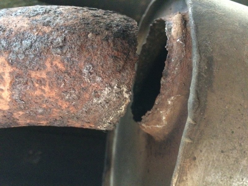
Halfway home from visiting the British Motor Museum at Gaydon Rangie developed quite a throaty rumble. Now whereas this made Rangie sound a bit more meaty than usual and was not unacceptable sound there was clearly an exhaust blow somewhere. Made it home without anything banging or falling off and investigation revealed this:

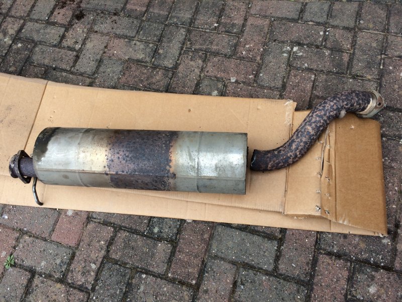
The exit from the rear of the centre silencer had given up just behind the weld - this had lasted for 13 years but it is a stainless steel exhaust that is guaranteed for life! Center section was duly removed:

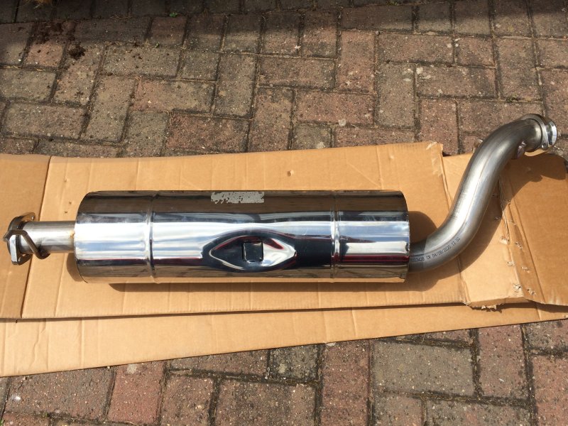
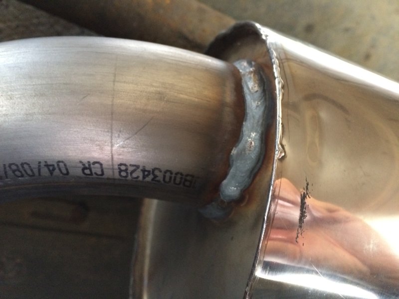
Claim made on the guarantee and this was duly delivered:

Installed today with new hangers and all back intact:

This section of exhaust failed previously in 2018 but just behind the joint where it couples to the tailpipes above the rear axle - that was repaired back then under the lifetime guarantee as well.